Automatic Transfer system (ATS)
Automatic Transfer System Explained in details.
Using the basic building blocks of utility power, system topology, on-site generation, and uninterruptible power supplies, the basic role of the automatic transfer system may now be defined.

In this role, the Automatic Transfer System must display the following characteristics:
- Robustness – it must operate as intended, even under abnormal power system conditions, without human intervention. Just as importantly, it must be able to distinguish when a system condition does not warrant transfer to the alternate power source.
- It must be able to control the switchgear as required and, additionally, must be able to pass the proper signals to the alternate power source if necessary (for example, to signal a generator when to start.
Simply stated, the role of the automatic transfer system is to provide the automatic transfer of power for its associated load group from a normal power source, such as a utility service, to an alternate power source, such as standby generation, in the event the normal source fails.
Example System Description
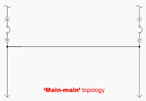
To fully illustrate the operational requirements ofa typical automatic transfer system, a more detailed representation of the system is required. For this purpose, the main-main topology arrangement used, but with the details of the automatic transfer system shown:
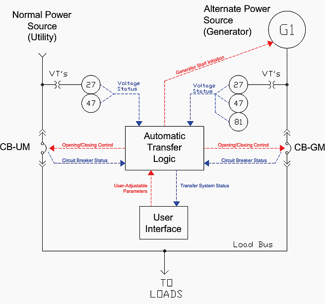
In Figure 1, the automatic transfer logic provides the decision-making for what automatic operations are to happen, and when. It controls the operation of the two transfer circuit breakers, CB-UM and CB-GM, and receives status inputs from those breakers. It also can initiate generator startup for the alternate power source.
Undervoltage (device 27) and negative sequence voltage (device 47) relays on each power source give the transfer logic indication of their condition. In addition, a frequency relay (device 81) is present for frequency indication of the
alternate power source.
Voltage transformers, or VT’s, step the system voltages down to instrumentation levels that can be used by these relays. A user interface allows the adjustment of certain operating parameters of the system, and updates the user onthe status of the system.
Using this example system, the operational requirements of a typical automatic transfer system will be examined.
Modes of Operation //
An essential requirement of anyautomatic transfer system is the ability to have different modes of operation. In a given mode of operation, the transfer system will respond in a given way to changing system conditions. For a different mode of operation, the transfer system will respond differently.
Two basic modes of operation, which any automatic transfer system must have, are:
- Manual Mode
- Automatic Mode
In the manual mode, the automatic transfer system does not perform any automatic operations, i.e., it does not respond to changing system conditions. All circuit breaker operations must be manually performed. Conversely, in the automatic mode of operation all operations, with a few emergency exceptions, are automatic, and the system will respond automatically to changing system conditions.
On the surface, this appears to be a simple arrangement, and to some extent this is true.
Good ATS design //
However, good automatic transfer system design has well-thought-out mode logic that answers the following questions:
- Can the system be placed into automatic mode if system conditions are not correct (for example, if an automatically-controlled circuit breaker is in the withdrawn position or not present in the circuit breaker cell)?
- What manual operations are allowed in automatic mode (for example, manual opening of circuit breakers)?
- What happens if an allowed manual operation is performed on an automatically controlled device (for example, if an automatically-controlled circuit breaker is manually tripped or trips due to a fault)
Such questions are not always easy to answer. In fact, they necessitate, in a well-designed automatic transfer system, the inclusion of a third mode of operation, typically known as auto mode failure.
The three modes of operation then typically work as follows:
1. Manual Mode
Selected via a selector switch position or other pre-determined user input via the user interface. No automatic operations occur.
Go back to ATS Operation Modes ↑
2. Automatic Mode //
Selected via a selector switch position or other pre-determined user input via the user interface. Attempting to enter automatic mode if the system conditions are not correct places the system into Auto Mode Failure.
In Automatic Mode, operations for certain circuit breakers (such as main and tie circuit breakers) are automatic, however manual tripping (or breaker trip due to a fault) of automatically-controlled circuit breakers is allowed. Such manual or fault-driven operations will result in the system being placed into Auto Mode Failure.
Go back to ATS Operation Modes ↑
3. Auto Mode Failure //
No automatic operations occur. For automatically-controlled circuit breakers, only manual tripping (or trip due to a fault) is allowed. To leave this mode of operation, the system must be placed into manual mode.
Of necessity, to make this mode logic arrangement function properly the breaker status must consist both of breaker open-closed indication and, for drawout circuit breakers, circuit breaker cell switch indication.
Circuit breaker cell switches are a feature which must not be overlooked as they are essential for the proper function of an automatic transfer scheme with drawout circuit breakers. For the same reason overcurrent trip switches for low-voltage circuit breakers or lockout relays for medium-voltage circuit breakers are also required.
Another question that frequently arises is that of a “test” mode of operation. While this could be made into a separate mode of operation, this is usually most expediently handled via voltage failure simulation test switches whilethe system is the automatic mode.
Go back to ATS Operation Modes ↑
Reference // Critical-Power Automatic Transfer Systems – Design and Application by Bill Brown, P.E., Jay Guditis, Square D Critical Power Competency Center


Comments
Post a Comment